THE WARCO WM180: A HOMEBREW THREADING DIAL.
This isn’t intended to be a treatise on how a thread dial indicator (“TDI”) works, or how to use one. For that, look elsewhere. But these points might be worth mentioning:
1. Good approximations of metric threads can be produced on a lathe with an imperial leadscrew, and vice versa, but a TDI won’t work when cutting a thread of a different “language” from that of the leadscrew, even with an exact 127T conversion gear.
2. A TDI is only a convenient way to get successive cuts in sync, and it is perfectly possible to cut any thread within the capability of the lathe and available changewheels with no TDI at all.
3. WM180 leadscrews are either 2mm pitch or 12 TPI, depending on whether the lathe is the metric or the imperial version. If metric, two different pinions (14 and 15T) are needed to cover all the standard metric coarse pitches from 0.5 to 3mm (but see note at the foot of this page). If imperial, a single 12T pinion will cover all whole numbers of threads per inch (like 40 and 16TPI), and a more practically sized 24T pinion will also cover threads like 11½ TPI (an American pipe thread, should you ever need one).
My imperial lathe came with no TDI, so I made one to help cut imperial threads. A pinion to mesh with the leadscrew (“LS”) would have to be a special, so I made one. I considered 12 teeth, but the gear would have an OD of about 1/3”, which might have been a bit fiddly to work on. So I went for 24T. In fact, my first effort was made by taking slices of the fatter end of the nylon(?) 24T bevel gear from a cheap toy hand drill from Proops Bros until I got to the point where it meshed reasonably. It worked fine, but didn’t survive being trodden on when the TPI found its way to the floor.

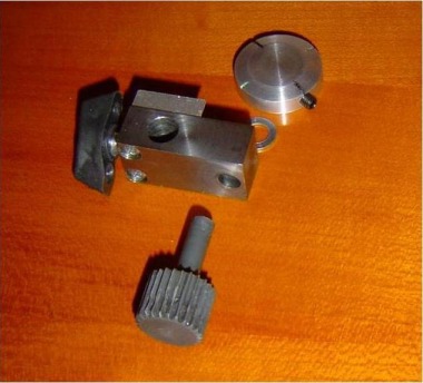
The component parts
I made a replacement pinion from a bit of 20mm round PVC bar. 24 threads on the LS occupy 2 inches, so to match that I needed a pitch circle circumference of 2” for my 24 teeth. Dividing by pi gave a pitch circle diameter of around 0.63”. The pitch circle lies about half-way up the teeth, so I turned the bar to 0.67” for the pinion, and ¼” for its integral shaft. To form the teeth, I set up changewheels on the banjo and a detent to give me 24 divisions in one full turn of the chuck. With a threading tool on its side in the toolpost and the topslide set parallel to the lathe axis, I gouged out the teeth in stages, winding the topslide along to propel the tool, down to a depth of about 0.07” in. This was all a bit rough and ready, and ignored niceties like pressure angle and the helix angle (or should that be the lead angle?) of the LS. However, all I wanted was a reasonable mesh. The dial is only an indicator telling when to close the half-nuts, and all the pinion does is turn the dial, so it is under negligible strain. Anyway, the pinion works fine.

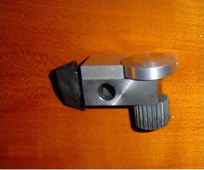
The assembled dial. The hole is for the mounting post, and the black object is the wing-nut style head of the setscrew which clamps the dial to the post.
The rest of the project was simple enough. An aluminium disc for the dial, fixed to the top of the pinion shaft with a grubscrew. A block with a vertical hole through it to take the shaft, and a horizontal hole and setscrew whereby the block could be mounted and dismounted from a horizontal post attached to the RH side of the apron, and swung round on the post in and out of mesh with the LS. A smaller block was fixed on top of the main one, to raise the fixed witness mark to the level of the disc.

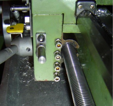
The mounting post, bolted to the side of the apron.

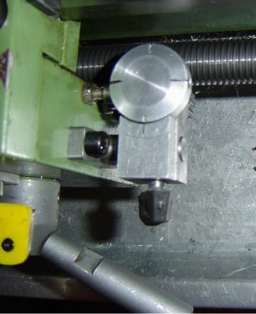
The thread dial indicator in position, with its pinion engaged with the leadscrew. It can be swung up on its mounting post to disengage it, or removed altogether.
Using a 24T pinion, rather than 12T, means that for any (odd or even) whole number of threads per inch the half-nuts can be engaged whenever either one of two diametrically opposed marks on the dial lines up with the witness mark. A second pair of marks means that the half nuts can be engaged on any of four marks to cut even (but not odd) numbered TPIs. I made these latter two marks rather shorter, so I could easily identify which two of the four I was using for odd number threads. With another four marks (eight in all), any mark could be used for threads divisible by 4, but I decided against that – better to wait a few seconds for a mark to come round than to risk mixing the marks up when a thread is half-formed. For threads ending in ½, only one of the four marks must be used. It’s a pity the dial marks don’t show up better in the photos
The modification wouldn’t win any exhibition prizes. But it functions perfectly, which is the main thing.
Pinions for metric TDIs.
The metric threads one would most probably want to cut are 0.5, 0.6, 0.7, 0.8, 1.0, 1.25, 1.5, 1.75, 2.0, 2.5 and 3mm pitch (corresponding to M3 to M27 coarse). A 15 or 30T pinion would cope with all but 0.7, 0.8 and 1.75mm. A 14T pinion would deal with those three, though dies might be thought preferable for 0.7 and 0.8mm, and 1.75 mm is only met with on M12 coarse. Accordingly, a 14T might be thought an unnecessary extravagance.
.
Back to Home and the Index
