THE WARCO WM180: A HOME-MADE BANJO WITH GEARS DEDICATED FOR FINE FEED.
Changing gears around on the quadrant or “banjo” can be a bit of a chore, and the set-up I use most often is a fine feed for plain turning. An extra banjo, permanently fitted with gears for a fine feed, is a real timesaver. Simply remove whatever gear is on the leadscrew, replace the stock banjo with the new one, and put a stock 80T gear on the leadscrew. The stock banjo is now used only for screwcutting.
Note: the pictures in the text are small. They are repeated in a gallery at the end of the page, where clicking on any of them will enlarge it.
Note: the pictures in the text are small. They are repeated in a gallery at the end of the page, where clicking on any of them will enlarge it.

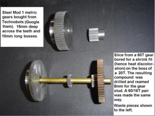
I found some cheap Mod 1 gears here in the UK at “Technobots” (Google them; usual disclaimer). Their largest is 60T, and I got two of those, plus a 20T and a 16T. My spindle gear is 40T, so with a stock 80T on my 12 TPI leadscrew, I would get just under 0.004” saddle movement per leadscrew revolution. The new gears were a lot thicker than needed, so I sliced them up (and spent a long time deburring) as shown in the photo. I bored out the two 60Ts so that the bosses of the smaller gears were a heat shrink fit in them; hence the discolouration in the compounded pair.

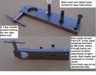
The new banjo is made from mild steel, and fitted with 8mm gear studs turned from silver steel, subsequently hardened and tempered. These have axial holes connecting with radial ones for lubrication, like the manufacturer’s gear studs. One is shorter than the others, and is for an idler – see below. The studs are drilled and tapped M6 in their bases, and held in place by M6 socket head screws. The screwheads are recessed into counterbores in the back of the banjo, and the clearance holes through the banjo are a little oversize to give wriggle room for adjusting the mesh of the gears.

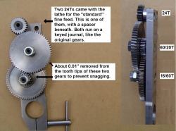
The topmost gear is an idler, with a spacer beneath. Without an idler, the new gear train doesn’t span the distance between leadscrew and spindle. I used one of the two 24Ts which came with the lathe for the idler. The only time both were needed was for the fine feed shown on the chart stuck to the lathe. I no longer need to set fine feed up on the original banjo, which is now reserved for screwcutting.

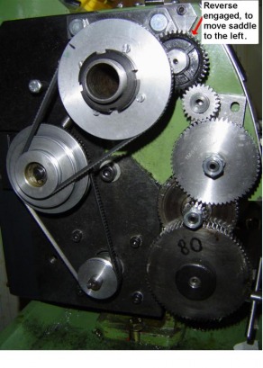
Adding the idler had the unwanted consequence of reversing the leadscrew, sending the saddle to the right when the spindle was running forward. Happily, I had already fitted my leadscrew reverse, so bringing this into play as a second idler gets things going in the right direction again. Of course, I might want a fine feed with the saddle moving to the right, and this can be arranged by swinging the “reverse idler” out of action, and meshing the 24T idler direct with the spindle gear. In this configuration, the stud for the idler lies behind the spindle pulley, so as mentioned earlier it is shorter than the other two studs.
Like the previous photos, this last one one shows a spare hole in the top of the banjo, which was for an idea that didn’t work (a lot of my ideas are like that...).
Arranging the studs so that none of the gears would foul anything on the outboard side of the headstock involved a full-size drawing, on which I shuffled separate prints on transparent film of (a) the outline of the banjo and (b) the pitch circles of the gears, piercing them with drawing pins to represent the leadscrew axis and the gear studs. No doubt those with CAD would manage things more easily!
The pictures below repeat those in the text, but clicking on any of them will enlarge it.


