ADDING A VARIABLE SPEED MOTOR TO A DORE-WESTBURY MILLING MACHINE
If you aren't familiar with the Dore Westbury milling machine, take a look at http://www.lathes.co.uk/dore%20westbury/index.html . My machine is the Mark 1 shown in the third and subsequent pictures. Stepped pulleys give three spindle speeds: 300, 800 and 1650 rpm. If the 8.8 to 1 epicyclic gearbox sitting under the spindle pulleys is brought into action to gear things down, those speeds are reduced to 35, 90 and 188 rpm respectively.
The original 40 year old induction motor began to need a yank on the pulley belt to get it going, and some of the internal insulation looked a bit dodgy. I began to think about a new motor, and decided that variable speed, as on my WM180 lathe, would give greater flexibility. According to various Web forums, the DC motors used in running machines (called treadmills in the US) are ideal for this sort of project.
Ebay revealed a faulty running machine only 3 miles away, and £15 secured it. Back home, it took five minutes to correct the fault.
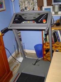
Here it is, cluttering up a corner of the kitchen before I dismantled it and removed the motor. This proved to be supplied by Leeson of Wisconsin, though the small print on its rating plate showed it was made in China. It was rated for 2 HP, 220V DC, 3400 rpm - a lot faster than the old 1450 rpm motor.
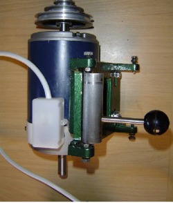
The new motor, with a bit of work done to drill and tap holes in its casing to match those on the DW's motor cradle, to fit secure brush covers and to add a plastic box to conceal the connection between the motor wires and the white cable which would supply pulse width modulated DC from the speed control circuitry. The flywheel and pulley have been removed and the 3-step pulley from the DW's original motor installed, after I increased its bore by a few thou from 5/8" to 16mm.
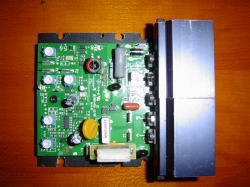
Here's the control board. The controller in the running machine couldn't be re-used - it was too big, and its speed was varied with push-buttons, rather than a simple knob akin to a volume control. I forked out £70 for a brand new KBIC 240* controller from a nearby stockist. Input is 230V AC (the UK domestic supply) and PWM output is 180V DC. The board is good for 2HP motors, when used with a heatsink. 2HP is overkill for this size of machine, so I don’t think the “undervoltage” (the motor is 220V) will make any practical difference. The dealer didn’t have the “official” £20 heatsink to bolt under the aluminium frame on which the board is mounted, and in any case underneath didn’t seem the best place for it. I bolted a couple of salvaged heatsinks to the upstand at the end of the frame, directly behind those semiconductors which were likely to get hot.
* The controller on my WM180 lathe seems to be very similar to a KBIC controller . A few notes on these controllers are on this page.
* The controller on my WM180 lathe seems to be very similar to a KBIC controller . A few notes on these controllers are on this page.
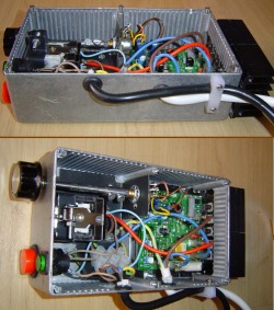
The scrap bin yielded a diecast aluminium box of the right size to accommodate the board, with space left over. A rectangular hole was cut into one end of it so the heatsink could stick out and get some air.
I incorporated the supplied potentiometer and a home-made “no-volt” switch comprising a 13A mains relay with a push-to-make switch to actuate the relay coil, wired so the coil would hold itself on until the circuit was broken by a push-to-break switch or by a mains power failure. The switch buttons are the usual green for go, red for stop.
I incorporated the supplied potentiometer and a home-made “no-volt” switch comprising a 13A mains relay with a push-to-make switch to actuate the relay coil, wired so the coil would hold itself on until the circuit was broken by a push-to-break switch or by a mains power failure. The switch buttons are the usual green for go, red for stop.
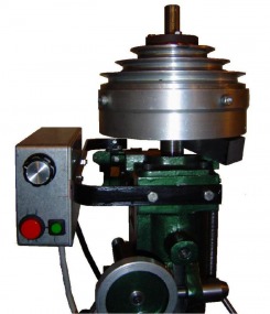
On the bench, I temporarily hooked up the new control box to the motor and verified that I could go from zero to top speed and back again at the twist of a knob.
Then I attached the box to a length of flat bar, bent up so it could be fixed to the front of the spindle head and the flange on the other end of the DW’s cross-tube. For clarity in this picture, the pulley guard is absent and the gearbox and pulley have been chocked up.
Then I attached the box to a length of flat bar, bent up so it could be fixed to the front of the spindle head and the flange on the other end of the DW’s cross-tube. For clarity in this picture, the pulley guard is absent and the gearbox and pulley have been chocked up.
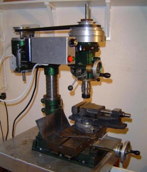
An overall view, with all major jobs completed. For a spindle rpm test, I used a bicycle speedo programmed so (a) it thought it was actuated by a magnet on a bike wheel of 1667mm circumference and (b) the readout was in kph rather than mph. The readout can then be translated from kph to rpm by multiplying by 10; e.g. its maximum reading of 199.9 kph equates to 1999 rpm. I held the actuating magnet in a fixture in the spindle.
Without the gearbox in play, turning the control knob varies the spindle speed from zero to 820, 1820 and about 3000 rpm, depending on the pairs of pulleys used. The 3000 figure is an estimate based on pulley ratios – it was outside the range of the improvised tachometer, and anything over 2000 rpm would be far too fast for the machine. I’ll only use that drivebelt setting in conjunction with the epicyclic gearbox.
With the 8.8 to 1 gearbox in play, speeds are from zero to 95, 205 and 340 rpm, but I have hardly ever needed the gearbox since adding the speed control .
To finish the project, I need to use my tachometer to mark up a set of interchangeable dials to slot in behind the control knob, so the machine can be set to run at chosen speeds. It’s a pity that there is simply nowhere on the spindle to fit a magnet or optical stripe to actuate a proper tachometer for direct readings.
UPDATES:
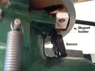
On closer examination, there's room for the tacho magnet on the bottom of the gearbox casing, against the rim - the bit of white plastic contains it. The sensor head (the part which is supposed to go on the front forks of a bike) is held on a bit of bent metal fixed under the rear two of the bolts which secure the top of the spindle head. I put a dummy magnet on the opposite side of the gearbox, to keep things in balance.
Of course, on the very rare occasions when the gearbox used, its casing is moored to the spindle head, so the magnet is immobilised and the tacho doesn't work, but a bit of arithmetic will get round that - see below.
Of course, on the very rare occasions when the gearbox used, its casing is moored to the spindle head, so the magnet is immobilised and the tacho doesn't work, but a bit of arithmetic will get round that - see below.
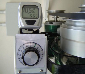
The tacho in action. It can be hard to read if light falls on it at the wrong angle, so it is on a bracket allowing it to be tilted for a better view. The 105.2 kph reading tells me the spindle is turning at 1052 rpm. Ignore the 5.65 reading - the tacho thinks I have cycled 5.65 km today.
I doubt there will ever be much need to find out the exact speed of the spindle in low gear, but just in case I retained a dial holder I made before realising that the magnet could be attached. It holds a simple dial (on paper, then laminated) with arbitrary 0 - 12 markings. With the gearbox out of action, the tacho can be used to set the speed at 8.8 times what I want and the dial reading noted. Then, the gearbox can be engaged and the dial set to the same reading to get low speed more or less right. If I did this at the dial reading shown in the picture, the spindle would be turning at 1052/8.8 = 120 rpm (near enough).
Footnote: the “bicycle computer/speedometer” is an “Echowell Star” at £9 from Halfords here in the UK. It reads up to a maximum 199.9 kph (representing 1999 rpm). Other brands sometimes only read up to 99.9 kph, which is probably quite enough for cyclists, but no good on a machine required to go over 999 rpm. The reading only updates about once a second, so a moment’s pause is needed after altering speed, to let things settle.
Since writing the above, and through the kindness of Mike of the Yahoo 7x12 Mini-lathe Group, I now have a better bike computer with a proper rev counter function. It's an "AS IIG" at £7 or so from Wilkinsons. The instructions specify 0 to 360 rpm, but a brief high speed test on the Dore Westbury got it reading up to 3450 rpm, so the instructions should probably say 0 to 3600. The Halfords computer can now go on my pushbike to encourage harder pedalling as I go out to buy The Times after breakfast.
I might add that my machine came with a car fan belt on the pulleys. I was getting a lot of vibration, resulting in circular gouges when I was taking horizontal surfacing passes with end mills and flycutters. There is some flex in the alloy castings on which the motor is mounted , and the motor seemed to be vibrating when cuts were in progress, setting up a wobble which made the spindle head bob up and down by 5 thou or so. As an experiment, the fan belt was replaced with 5/16” clear plastic round belt from Chronos: http://www.chronos.ltd.uk/acatalog/Engineering_Menu_Plastic_Transmission_Belt_46.html . I think it’s a cheap version of Redthane belting, and it is joined by pressing the ends on either side of a heated knife blade or similar, then withdrawing the blade and pressing the melted ends together until the plastic sets. It is “stretchy” and I made my belt about 5% undersize. As I write, it has been in place for a couple of months. Perhaps the elasticity of the belt soaks up the vibrations, because they have disappeared and surface finish is much improved.
Back to Home and the Index
