THE WARCO WM180: A HANDWHEEL AND DIAL FOR THE LEADSCREW.
A handwheel on the leadscrew (“LS”) is useful. Sometimes, it isn’t worth the bother of setting up power feed for a quick job, or trying to set the topslide exactly parallel and using its rather fiddly handwheel. The carriage handwheel offers manual feed, but with only coarse control, and there’s a lot of backlash on the rack.
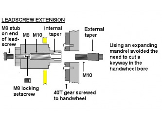
Adding a handwheel isn’t hard. There’s an M8 stub on the end of the LS, with a long nut to adjust endfloat - long because there’s a hex socket grubscrew inside it, pushing on the end of the stub to lock the nut. The nut can be replaced with an extension for the LS projecting beyond the end of the lathe bed, where a handwheel can be fitted.
My first effort also carried a dial, but graduating this was a problem. One turn of my imperial LS moves the saddle 1/12" or 0.0833” (though I doubt if Chinese leadscrews are quite that accurate). I settled on 84 divisions, each representing one thou. An approximation, but at least the error was on the safe side, leaving cuts a tiny bit short – better to take off too little than too much. Arithmetic was needed for jobs like turning down the end of a bar over a 0.200” length. That would take two full turns (0.168”) plus another 32 thou, and then the result would be nearly 1 thou short, because of the approximation. Sometimes, I wished I’d bought the metric version of the lathe!
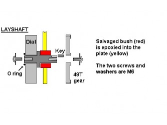
Salvation was at hand. Because they were only about £6 and might come in useful sometime, I once added a set of plastic changewheels for a Sieg C2 lathe to an order from Arc Euro Trade. The set included 40T and 48T gears. With the 40T attached to the handwheel driving the 48T on a layshaft carrying the dial, the dial would revolve so that 100 graduations would each represent one thou saddle movement. No more need for mental arithmetic. Of course, there is backlash between the gears, but in the end this added less than half a thou to the existing 6 thou lost motion attributable to the half-nuts.
The handwheel could have gone on the layshaft, so each turn would shift the saddle exactly 0.1 ” to make counting easier, but far more rigid construction would have been needed.
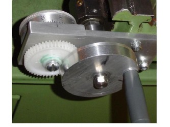
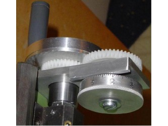
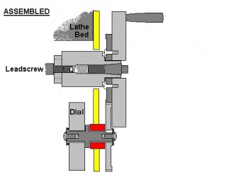
Other than the gears, everything was made up from oddments. There are no drawings, but the following photos, notes and sketches may help. Click on any image to enlarge it.
Notes:
1. Remember that the grubscrew needs to be removed (and kept for re-use) before the original long nut can be removed.
2. The LS extension passes through an ample clearance hole in the aluminium plate which carries the layshaft. My layshaft runs in a bush salvaged from an old windscreen wiper and epoxied into a hole in the plate.
3. To mark up the dial, I indexed the spindle with a detent on a 60T gear mounted on the banjo, compounded with a 24T driving the 40T spindle gear via an idler. Care was needed to take up the backlash in those gears before scribing each mark with a threading tool mounted edge on in the toolpost.
3. The 48T gear is keyed to the layshaft, on which the dial is free to revolve so it can be zeroed. A sandwiched O ring adds friction to hold it in place.
4. The carrier plate is bolted to the end of the lathe bed. The bolt holes are oversize, allowing the gear mesh to be adjusted by moving the plate.
5. If the handwheel is too big, it will prevent removal of the tailstock – the TS clamp plate will foul the handwheel. I found this out the hard way, of course!
Sketches - click on any of them to enlarge it:
