THE WARCO WM180: AN IMPROVED TOPSLIDE SWIVEL.
UPDATE: The modification described here is not possible on the newer WM180s - see A More Modern WM180. At the foot of this page is a link to some simpler mods which will work fine on the current (2012/13) machine.
Owners of these lathes soon discover that altering the top-slide angle is a bit of a pain.
It involves winding the slide a long way back to get at the bolts through its base. These pass through the topslide base into threaded holes in a disc under the cross-slide, so the cross-slide is sandwiched between disc and topslide base. When tightened, the bolts pull the topslide down on to the cross-slide, to secure it.
A better arrangement is possible. A new disc is bolted permanently to the topslide base. The disc is flanged. A plate with a matching flange pulls down on the disc, and hence pulls the topslide down, clamping it to the cross-slide. The clamp plate is tightened down using “out in the open” bolts through its corners, running into tapped holes in the cross-slide.
The old system can be restored if needed, though I can't see myself wanting to do that.
Here are sketches of the new arrangement:
Disassembled - new components shown in grey:
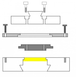
< Original clamping bolts
< Topslide base
< New clamping bolts
< Clamp plate
< New disc
< Cross-slide. Position of old
discarded disc shown in yellow
As shown in the "Assembled" sketch below, the original clamping bolts are re-used to bolt the new disc hard up to the top-slide base - there will be no further need to loosen/tighten them. The new clamping bolts go through each corner of the clamp plate into tapped holes in the cross-slide.
Assembled:
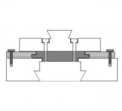
Each "step" in the clamp plate needs to be a little shallower than the corresponding step in the new disc, to allow (a) the disc and topslide to swivel when the corner bolts are loosened and (b) the clamp plate to pull down on the disc when the bolts are tightened, thus pulling the topslide hard down to the cross-slide. The steps in my clamp plate are each 2.75mm (total 5.5mm). The corresponding steps in the new disc are each 3mm, so there is 6mm of the new disc's thickness sitting on top of the cross-slide.
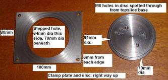
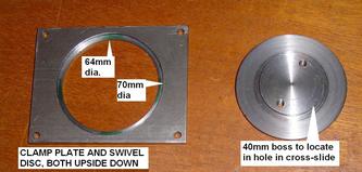
The new disc has three different diameters: a shallow (actual depth doesn’t really matter) 40mm boss on the bottom to locate in the 40mm hole in the cross-slide which housed the original disc, above that a 70mm flange 3mm deep, and on the top a 64mm section, again 3mm deep. The 40mm diameter should be a good sliding fit in the hole in the cross-slide, but the 64 and 70mm dimensions aren't critical, as long as the stepped hole in the clamp plate matches them. The hole through the 80 x 100 x 5.5mm clamp plate is bored to 64 and 70mm diameters to form an internal flange to correspond with the new disc. The four new clamp bolts are M5. Their clearance holes through the corners of the clamp plate are centered 6mm in from the edges at each corner. Plain hex head, rather than socket-headed, bolts are used. When the topslide is at an angle, parts of it will overlie the bolts and prevent access with an Allen key, but a spanner can be slipped on from the side.
Here are photos of both sides of the disc and clamp plate - clicking on either picture will enlarge it, so the labels can be seen:
Construction notes:
1. Make the clamp plate first, cutting the stock to a rectangle a bit bigger than 80x100mm - say 90x110mm. Then drill/bore the stepped hole through its centre (where corner to corner diagonals cross).
2. Now turn the the 40mm diameter of the new disc, then its other two diameters to fit the hole in the clamp plate. It's usually easier to turn a part to fit a existing hole than the other way round.
3. Remove the topside and the old disc from the lathe. Getting the old disc out involves removing the cross-slide - take off the little plate at the back of the saddle which limits the slide's rearward movement, and wind it back off its feedscrew. Mark the positions of the two holes in the new disc through the topslide base, drill them 5mm and tap M6.
4. Using the original bolts, fasten the disc to the topslide base, with the clamp plate sandwiched between the two. Put this assembly on top of the cross-slide, with the 40mm boss located in the hole in the cross-slide.
5. Scribe the outline of the cross-slide on to the underside of the clamp plate. Dismantle and cut, file or mill the clamp plate down to final size. Drill the four corner holes 4.2mm (the tapping size for M5) centred 6mm in from each adjacent edge.
6. Reassemble and replace on the cross-slide. Drill (4.2mm) through the corner holes in the clamp plate into the cross slide, and tap M5. Watch out for the cross-slide gib adjusters, particularly at the rear right-hand hole. I drilled about 10mm deep, and used hex headed bolts with threaded sections cut to 14mm long, to pass through the clamp plate and allow a reasonable depth of thread engagement. Remove the clamp plate and drill the corner holes out to 5mm.
7. Replace the clamp plate on the cross slide, insert the four clamp bolts and test the new swivel.
Of course, having 6mm of the disc's thickness sitting on top of the cross-slide will raise the top-slide and toolpost by 6mm, leaving tools well above centre height in the stock 4-way toolpost. There is plenty of metal in the base of the toolpost, so 6mm can be milled or faced off the underside to lose height (note: facing might be difficult if your only toolpost is gripped in the chuck - time to phone a friend!). A counterbore will be needed, to accommodate the flange at the base of the toolpost stud. I took 4mm, off the bottom of the toolpost, then lowered the tool slot floor by 2mm on one side to take 6mm and ¼” tools, and by 4mm on the opposite side by to take 10mm and 3/8” tools. That was a mistake; the slots were then so deep that the toolpost bolts weren't long enough to reach the top of the tools, so I had to use packing on top of them. The quick change toolpost which I have since acquired allows for easy tool height adjustment, and would have made it unnecessary to modify the stock 4-way one.
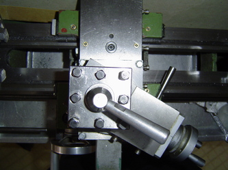
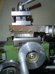
Below are photos of the new swivel, in place. The left-hand one shows how the topslide can obscure one or more of the clamp bolts, so there's no access for an Allen key> But there is plenty of room for a spanner to slide on to an ordinary hex head from the side - see the right-hand picture, which also shows the clamp plate below the protractor, and the modified toolpost. Click on either image to enlarge it.
I understand that this mod can't be easily accomplished on a "7x Mini-lathe" of the Seig or Real Bull type, because the swivel disc is closer to the operator's end of the cross-slide. There isn't room to fit the front two clamp bolts without the corners of the topslide base fouling their heads as it is swivelled round.
Max Jensen in Denmark and Marcello in Italy have devised much simpler ways to make swivelling the topslide easier.
Back to Home and the Index
Back to Home and the Index
