THE WARCO WM180: EASIER BELT CHANGEOVER BETWEEN HIGH AND LOW SPEED RANGES
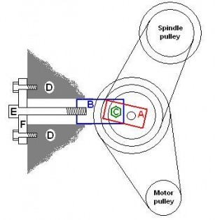
Switching the upper drive belt from pulley to pulley isn’t easy. On the sketch below, block B has to be unclamped from the large steel plate D by loosening bolt C (shown as hex-headed, but mine only had two flats on it) which is hidden behind the middle pulley. When released, block B will slide to the right along the slot in plate D as Allen bolt E is undone. This slackens the belts so the upper one can be changed between pulleys. Bolt C runs through both Block B and Block A, so when C is loose Block A can swing and distribute tension evenly between the upper and lower belts as they are tautened up again by tightening up bolt E against "bridge piece" F. When the belts are taut, Blocks A and B are clamped down to plate D again, by tightening bolt C.
Being hidden behind the middle pulley, bolt C has to be loosened and tightened by feel. So does Allen bolt E - awkward if your lathe is against a wall. It’s all very fiddly, and the air can turn blue.
Furthermore, it turned out that bolt C went into a simple big washer and a nut behind plate D, and the bolt was so long that it was pushing to and fro among the wires in the box holding the electronics. I thought that was unsatisfactory.
The cure (best executed in reverse order):
1. Replace bolt E with a T-handled bolt, long enough to stick out at the back of the lathe and give clearance for the T-handle to turn. A semicircular cutout as shown here.is needed in the rear edge of the gear cover, through which the new bolt can project, No more fiddling around with an Allen key at the back of the lathe!
2. File a groove across the head of hidden bolt C, and braze a bar to it with the end sticking out from behind the middle pulley. Care is needed in positioning the groove, so the tommy bar doesn’t foul the pulley spindle as it is tightened up. Once done, a quarter turn is enough to release the Blocks A and B. No more fishing around with a spanner behind the middle pulley, trying to find the flats on a hidden bolt!
3. Replace block B with a proper T-nut to slide in the slot, with a low profile inside the electronics box. Two tapped holes have to be provided in it, for bolts C and E.
Warning – access to the rear of plate D is required, which involves removing the cover plate over the electrics and delving amid the wiring. Make sure the lathe is unplugged from the mains throughout.
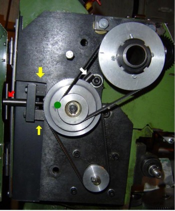
The photo below is of the lathe after modification. The green dot shows the the position of bolt C under the pulley, the white arrow indicates the tommy bar on bolt C peeping out from behind the pulley, the red arrow the tensioner T-handled bolt and the yellow arrows a couple of spacers under bridge piece F. The spacers are to take up belt slack after I installed a smaller pulley on the motor - see below.
,
Also in the photo is a smaller (35mm) motor pulley which I made to reduce speed and increase torque, each by about 30%. The top speed of the lathe is now down to 1850 rpm, but I don't work on tiny diameters so don't really need anything above that. The smaller pulley left the belt too slack for the tensioner to pull it taut, so I added the spacers shown with yellow arrows to get it tight. At the very top of the photo, the arm behind the top pulley carries my leadscrew reverse gear.
Back to Home and the Index
Back to Home and the Index


