This page has nothing whatsoever to do with the Warco WM180. It's about an old (1960s or early 70s) Perris baby lathe....
....which I bought around 1985, simply because a friend of mine only wanted £25 for it, complete with 4-jaw chuck, collet chuck, tailstock chuck, faceplate, vertical milling slide, centres and some miscellaneous tooling. Its vital statistics are a centre height of 1.75" (2.5" in the gap) and 8" between centres.
The Perris SL90 was the immediate forerunner of the Cowells 90ME. Indeed, after Cowells took over Mr Perris's business, they produced his lathe unchanged for a period, after which it gradually evolved into the current Cowells 90ME, which still strongly resembles its ancestor, and into the 90CW for horologists. I don't know if Cowells ever supplied their machines in kit form, but that's how my Perris was purchased, judging by the dog-eared assembly instructions which came with it. These contain the following reassuringly short list of the essential tools required:
Small flat smooth file Medium size screwdriver Set of Allen keys
Emery cloth - medium and fine 1/2" wide paint brush Small hammer
Whoever built mine seems to have done a good job; there's not a file or hammer mark in sight!
A couple of pictures of the lathe as it now stands - click on either of them to enlarge it:
Both photos are recent. The top view shows the goodies which arrived with the lathe all those years ago, together with the on-off and reverse switches. In the side view, I have obscured the motor for clarity. The chunk broken out the cross-slide T slot was there when I got the lathe, honest! The slide has since been replaced with an apparently unused one I was lucky enough to be offered.
Behind the headstock there is a back-gear, useful for difficult jobs as the motor is only 1/12 HP. There is no leadscrew reverse, so left-hand threading would require a modification which I've never made because I have no changewheels other than those for the "Auto Traverse" or fine feed. The lever under the headstock operates a dog clutch on the leadscrew, which can be arranged for automatic disengagement when the carriage has travelled left to a point set by the operator.
No half-nuts are provided. The carriage is permanently engaged to the 1mm pitch leadscrew, but when changewheels are present, making the leadscrew handwheel impossible to turn, the leadscrew can be disconnected using the dog clutch, and the handwheel used to move the carriage. The lack of half-nuts and a carriage handwheel operating a rack and pinion is, I feel, a shortcoming - the carriage can only be repositioned by the leadscrew handwheel, or via the auto-traverse. With such a fine pitch, either of these operations takes time. The modern Cowells shares this deficiency, but I suppose there isn't really room for half-nuts, a handwheel and associated pinions and a rack, though I have one or two ideas which I might try if I get the time.
UPDATE: I have now made and fitted an apron with a half nut. Details here. I have also modified an M14x1 3-jaw chuck to fit the obsolete spindle thread, as shown here.
The dials on the cross slide, topslide, leadscrew and tailstock ram are all adjustable to zero. They are marked in thousandths of an inch, which is an approximation because the screws are metric. The fiction that 1mm equals 0.040" is used.
The lathe is still capable of useful work. I used it to skim 2mm off the bottom of the 60mm square "4-way" toolpost on my Warco lathe. The Perris coped admirably with the facing cuts, despite them being interrupted until I was well within the corners.
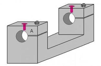
In 2008, disaster struck. A design fault of the Perris (and early Cowells lathes) is that the spindle journals are near the top of the headstock, with little cast iron above them, and there are vertical oil holes through the thinnest parts. Adjustment for wear is by simple pinch bolts. This very rough sketch shows the view from the outboard side, with the oil ports in pink:

Well, you can guess what happened. I thought I detected a bit of play in the outboard bearing, tightened down its pinch bolt a fraction, and was rewarded with a terminal sounding crack as the headstock cracked at its weakest point and the part marked "A" broke away.
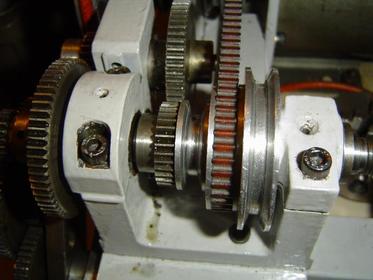
A new headstock from Cowells was out of the question (£££) and dimensions may have varied a bit over the years, anyway. The location to the bed has definitely changed from a long loose tenon to dowel pins. But, by now I had my Warco lathe and a milling machine. I turned a piece of good quality round cast iron bar down to about 2" diameter, drilled/bored/reamed it 1/2" to match the spindle, sawed across so I had a full semicircle, and did a bit of milling and drilling to shape it up a bit and provide for a clamp bolt on each side, and an oil hole. Then, I sawed off and milled the broken end of the headstock so it was level, drilled and tapped for the second clamp bolt, and fitted the new "half bearing" on the top. I fiddled about with shims until it felt just right, and that was it. The next picture shows the completed repair, and all seems well with the lathe again. I must be very careful over the bearing on the chuck end of the headstock. As the photo and sketch show, there isn't enough room to fit another clamp screw on the far side of that bearing, so it couldn't be repaired in the same way.
A new headstock from Cowells was out of the question (£££) and dimensions may have varied a bit over the years, anyway. The location to the bed has definitely changed from a long loose tenon to dowel pins. But, by now I had my Warco lathe and a milling machine. I turned a piece of good quality round cast iron bar down to about 2" diameter, drilled/bored/reamed it 1/2" to match the spindle, sawed across so I had a full semicircle, and did a bit of milling and drilling to shape it up a bit and provide for a clamp bolt on each side, and an oil hole. Then, I sawed off and milled the broken end of the headstock so it was level, drilled and tapped for the second clamp bolt, and fitted the new "half bearing" on the top. I fiddled about with shims until it felt just right, and that was it. The next picture shows the completed repair, and all seems well with the lathe again. I must be very careful over the bearing on the chuck end of the headstock. As the photo and sketch show, there isn't enough room to fit another clamp screw on the far side of that bearing, so it couldn't be repaired in the same way.
Wick lubricators for the spindle.
As can be seen above, lubrication of the spindle is via vertical oil holes, 2mm diameter and countersunk at the top. Oil drains down them pretty quickly, but this is a total loss system and sufficient oil will remain in the bearings for an hour or so of running. Oil is lost as it oozes out of the bearings along the spindle. Indeed, the result of filling the oil holes while the spindle is turning is an annoying spray of oil thrown off the backgear bull wheel and pulleys.
A way to stop the oil draining down so quickly was needed. All the oil would ultimately find its way out along the spindle, but it seemed a good idea to stop it coming out in a rush every time new oil was added.
A little research revealed that wick lubricators might do the trick. They work like a siphon, with capillary action slowly drawing oil up from a reservoir and then sending it down to a bearing.
They were easy to make. Simple drilling and parting off created two little oil cups (internal dimensions 6mm deep and 8.5mm diameter), with 2mm holes in their 6mm thick bases. Lengths of 2mm o/d brass tube were soft soldered in to the bases, top ends just proud of the oil cup, and sufficient projecting below the base to fit almost to the bottom of the 2mm dia. oil holes in the headstock.
Wool (pure; not blended with synthetics) is best for wicks. Worsted is recommended, but embroidery/tapestry wool seems satisfactory. This was drawn through the tubes using a hairpin-shaped piece of thin wire as a needle. The bottom end was trimmed flush with the tube. Around 8mm was left sticking out at the top, with a bit of solder crimped on as a weight to keep it submerged in the oil.

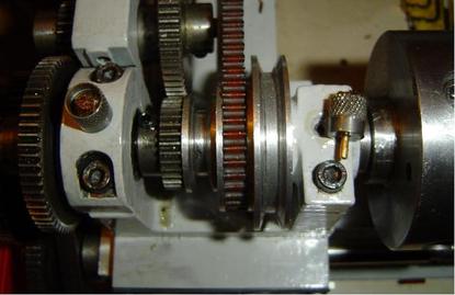
This shows one oiler in place and the other withdrawn from the oil hole in the headstock. They were knurled before being drilled out, to give a good grip. If left in place when the lathe is idle, any remaining oil in the reservoirs soon drains through, so when I am finished, I pull them out and wipe the contents over the lathe bed etc.
The oilers take about three hours to empty. They each hold about 0.35ml of oil. That doesn’t sound much, but it represents about 10 drops, and received wisdom is that one drop an hour is enough.
The oilers take about three hours to empty. They each hold about 0.35ml of oil. That doesn’t sound much, but it represents about 10 drops, and received wisdom is that one drop an hour is enough.


