Richard's WM180, bought in December 2012.
I bought my WM180 in 2006/7, and the one Richard bought at the end of 2012 shows a few changes over the last five or six years. Incidentally, the publicity photos at Warco and other sellers of the same machine under different names do not yet (early 2013) seem to reflect these changes.
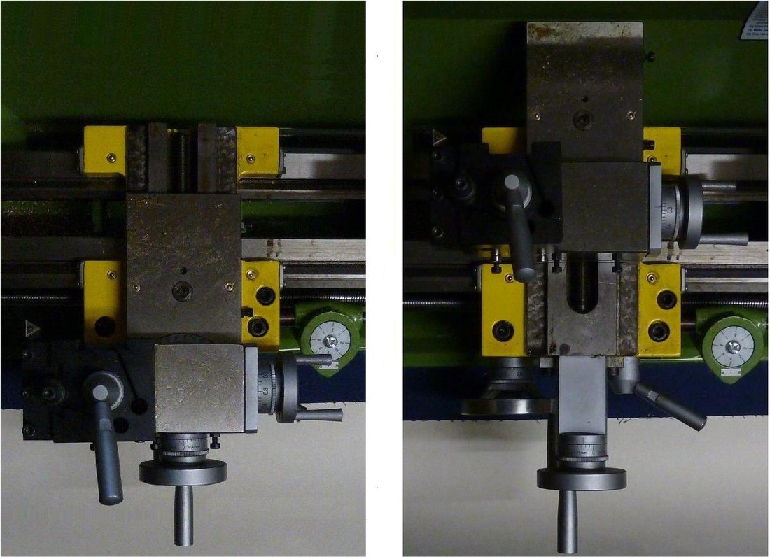
The most important change is that the axis around which Richard’s top slide revolves has been moved further out towards the operator. As will be seen from the pictures below, when the top slide is set parallel to the bed, the side of its base is flush with the end if the cross slide. When my own top slide is in that position, its base is 20mm in from the end of the cross slide, allowing room for the protractor casting. Richard’s protractor is behind his top slide.
One picture shows the cross slide wound right out. In the other, it has been wound in to the point where its nut has just detached from the feedscrew. The revised position of the top slide means that the tool can be brought further out, allowing larger diameters to be turned without undue contortion of the top slide and toolpost. However, with his cross slide wound fully in, the axis of Richard’s top slide swivel will not go as far in towards the lathe’s centre line as mine does. This might make my criticisms of the vertical milling slide even more pertinent.
My top slide swivel would not be feasible on Richard’s lathe, but the simpler topslide swivels made by others would be fine.
My slides each have four adjustment screws for the gibs, plus a fifth central screw on the cross slide which can be used for locking it. Richard only has three adjusting screws on each slide, and no locking screw. In my view the more support a gib gets from adjusting screws, the better. It would be relatively simple to add extra ones, of course. Another two on each slide would allow the existing central ones to be used as locking screws.
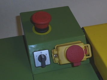
One good idea is an emergency stop switch on top of the little switch housing perched above the headstock. On my older lathe, the only E-stop is the yellow cover with the red button, but the additional one on top will be easier to hit in case of trouble.
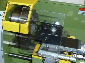
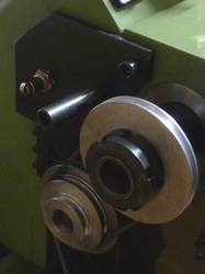
There are two safety switches on the newer lathe, both of which cut off power to the motor. One operates if the hinged guard over the chuck is raised. My lathe had this arrangement, until I removed the guard altogether. The other switch is inside the gear cover, operating as the cover is removed. This photo also shows the transparent chip and coolant shield which is now attached to the top slide. Richard reports that this obstructs access to the toolpost, and it will probably be removed; it looks vulnerable to knocks, so it might well remove itself before too long. Incidentally, the toolpost shown in Richard’s pictures is a quick change version, not the standard one.
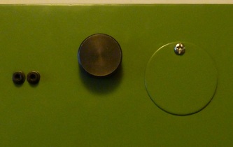
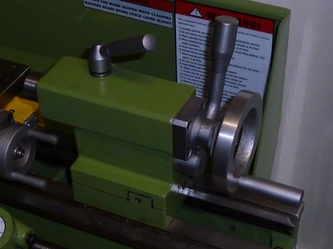
Some fairly minor changes are the replacement of the knurled nuts which retain the gear cover with captive nuts which can’t be mislaid, and a revised camlock for the tailstock. This last merely involves the rotation of the mechanism through 90°, when compared to my older tailstock. Finally, there is now a little swing-aside cover over the hole in the gear cover through which long stock passing through the spindle can project. The pictures below show these features, and clicking on any of them will enlarge it.
