THIS MISCELLANY CONTAINS:
A pull-out swarf tray
A convenient lever for the saddle lock
A DTI holder for the toolpost
A spindle handcrank
Correcting the markings on the topslide dial
A pull-out swarf tray
A convenient lever for the saddle lock
A DTI holder for the toolpost
A spindle handcrank
Correcting the markings on the topslide dial
A pull out swarf tray

Sweeping swarf out from beneath these small lathes can be surprisingly time-consuming. And stirring the sharp stuff around to find the masterpiece you have just parted off can be hard on the fingers. To make life easier, I bent up a supplemental tray from 1mm aluminium sheet. This slides out, allowing anything valuable to be recovered before the junk is dumped into the bin.
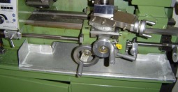
A paper template was followed by much cursing with tinsnips and nibbler, and bending to shape with the aid of a B&D Workmate and odd lengths of wood. Most of the holes and gaps at the corners were filled up with “Milliput” epoxy putty. The tray is easy to remove and replace. Its back edge projects a little beyond the bottom of the rear chip guard, to collect swarf which drops down at the back.
A lever-operated saddle lock
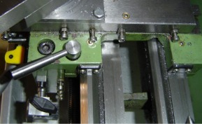
To save hunting for the right Allen key, and then finding I couldn’t use it because the topslide is positioned over the saddle lock bolt, I made this lever operated version. The picture shows the saddle locked. To release it, turn the handle 1/3 of a turn so it points towards the rear of the lathe. It’s very convenient for rigidity when parting off. I have since screwed a little peg in the green surface to the right of the lever, to prevent it going so far anti-clockwise that the end of the lever jams against the gib adjusting screws as the cross-slide is wound out.
I’d like to do something similar for the cross-slide clamp screw (the one like a gib adjuster without a lock-nut), but there’s no room. Update: there is room. The locking screw has been replaced with a mini version of the cross slide lock, with a short lever which rests against the gib adjuster to the left when undone, and almost touches the one to the right when clamped up. If the lever was vertical when clamped up, it might foul the topslide base when that was set at odd angles.
I’d like to do something similar for the cross-slide clamp screw (the one like a gib adjuster without a lock-nut), but there’s no room. Update: there is room. The locking screw has been replaced with a mini version of the cross slide lock, with a short lever which rests against the gib adjuster to the left when undone, and almost touches the one to the right when clamped up. If the lever was vertical when clamped up, it might foul the topslide base when that was set at odd angles.
A DTI holder for the toolpost.
My DTI is the common cheap variety. I have a magnetic stand, but it’s hard to find a flat seat for it, and to arrange its arms into the right position without knocking the fragile DTI on something. Each of the "one screw" clamps on the arms has too many functions, permitting sliding, swivelling and, in the case of the outer clamp, gripping the DTI. It can slip off and fall if I'm not careful, and is a pain to dismantle and repair.
Usually, I have the DTI with its finger at centre height to true up a workpiece by reference to (a) its cylindrical surface, (b) a hole in it or (c) its flat front face. With a DTI holder clamped in the toolpost, the cross- and top-slides can be used for precise positioning. Height is set by clamping the holder at the right level in the dovetail of my quick change toolpost. If you have no QCTP, it wouldn’t be difficult to make a similar holder, designed so the DTI finger is at centre height when the holder is clamped in the standard 4-way toolpost.
Further adjustments to the DTI's orientation can be made by rotating it around on its fixing post, by setting a subsidiary holder (when used) at different angles in the main block and by swivelling the entire toolpost on its mounting post.
One photo shows the components. The other two (staged off the lathe for clarity) show how the DTI can be set up in the holder.
I milled the dovetails, but a fit achieved by reasonably careful filing would be good enough to secure the DTI firmly.
Click on a picture to enlarge it.
A spindle handcrank
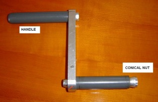
It may seem odd to buy a machine tool and then power it by hand, but a crank can be very useful when cutting threads, and essential (for me, at least) when cutting them with a tap or die held in the tailstock. In this mode, the lathe is only being used as a jig to hold everything in line and ensure that the thread starts true.
I had some 20mm PVC bar which was a nice sliding fit in the spindle bore. A conical nut in a tapered hole expands it slightly to fix it in place, when tightened up with a long bolt. The bar is such a good fit that it expands sufficiently without needing any collet-type slits. Undoing the long bolt by one turn, followed by a light tap with the spanner, loosens its grip.
More PVC bar was used for the handle, and a piece of aluminium formed the crank.
Don’t forget to remove the thing before switching on the motor, because (a) it makes the lathe severely unbalanced, and (b) it can give you a whack if you get in the way. Learning from my mistakes, I now unplug my lathe while hand cranking, as a reminder to remove the crank before starting the motor. With hindsight, a wheel rather than a crank would be safer – better balanced, and nothing to flail around if the motor is started with it still in place.
A topslide dial problem
My lathe is imperial, but the only really imperial thing about it is the 12 TPI leadscrew. The feedscrews on the cross-slide, topslide and tailstock are all 1mm pitch, though the dials are marked in thousandths of an inch on the fiction that 1mm = 40 thou (rather than the true 39.37 thou). So, those feedscrews should all have dials with 40 divisions.
Well, two of them did, but the one on the topslide, though clearly marked as being calibrated in thousandths, had 50 divisions. I checked the topslide advance – just over 39 thou per revolution.Some Chinese person had fitted the wrong dial. Because I don’t use the topslide dial for measuring, even when threading with the slide set over at an angle, it’s taken 4 years to realise something was wrong. But you know how it is – once noticed, things like this nag at you until you do something about them. So I resolved to engrave new graduations.
I liked the look of Mike Burdick’s method (of scribing the marks, not stamping numbers) at:
http://www.neme-s.org/images/PDF_Files/Making_Graduated_Collars1.pdf .
He uses a long boring bar type tool with a slender V bit, plunging in at the inner end of the mark and pulling the bit out over the edge of the dial, rather than pushing in from the edge.
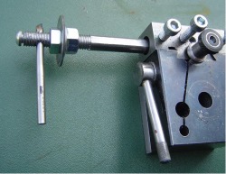
It struck me that there was an easier way to get the graduations to the right length than his method of measuring each one individually using his handwheel dials. Here’s my rough and ready tool, holding an HSS V bit; no point cutting off the excess, because the full length might come in useful sometime. Note the threaded section carrying a washer secured between two nuts.
With the dial collar on a mandrel, the existing markings were turned off. Forty new graduations were needed, with every 5th and 10th being longer than the rest. Happily, WM180 spindle gears have 40 teeth, so an improvised detent was made by bolting a changewheel immoveably to the top of the banjo, so it could be swung in and out of mesh with the spindle gear to do the indexing. This trick would also work for spindle indexing by any number which divides into 40, i.e. 2, 4, 5, 8, 10 and 20..
With the dial collar on a mandrel, the existing markings were turned off. Forty new graduations were needed, with every 5th and 10th being longer than the rest. Happily, WM180 spindle gears have 40 teeth, so an improvised detent was made by bolting a changewheel immoveably to the top of the banjo, so it could be swung in and out of mesh with the spindle gear to do the indexing. This trick would also work for spindle indexing by any number which divides into 40, i.e. 2, 4, 5, 8, 10 and 20..
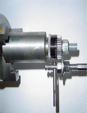
The dial collar was blacked up to make the marks more visible. This next pic shows the short “unit” markings being applied using the washer as a depth stop against the fat washer holding the work on the mandrel – as can be seen, the “fat washer” is actually an old gearwheel which just happened to be the right bore and diameter. Then, it was just a matter of winding the carriage handwheel until the depth stop made contact, plunging in with the cross-slide (using its dial for uniform depth of cut), dragging the tool to the right with the carriage handwheel, withdrawing the cross-slide, indexing round by one gear tooth and repeating.
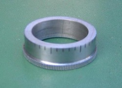
I engraved 32 short marks in sets of four with a gap between each set, then reset the depth stop and put in 8 longer ones for the 5s and 10s.
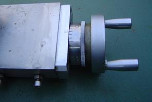
Mike Burdick’s method of whacking numbers into work held in the chuck doesn’t sound as if it does the spindle bearings and chuck much good, so I did the job off the lathe, using a jig cobbled up from MDF. The dial remained on the mandrel to avoid distorting the collar or leaving bumps on its inner surface as the numbers (0, 10, 20 and 30) were stamped. This rather poor picture shows the dial back on the topslide


