A half nut for the Perris
As mentioned on the other page relating to my Perris lathe, I was always annoyed by the time involved in moving the saddle when repositioning it by anything more than a short distance. On the Perris, the leadscrew nut is solid, and it takes forever to traverse the saddle either by hand or under power. Bigger lathes have half nuts to disconnect the saddle from the leadscrew, and a carriage handwheel operating a rack and pinion to traverse the saddle quickly.
Though a pair of half nuts would be impractical because there’s little space above and behind the leadscrew, I thought a single half nut under the leadscrew would work. There definitely isn’t room for a rack and pinion. I considered a chain and sprocket arrangement behind the lathe, but that would be cumbersome. However, after the leadscrew nut was unbolted so the saddle could be pushed to and fro by hand, it proved easy enough to move, despite the saddle gib being well adjusted. This crude but simple solution was adopted, leaving only an apron and half nut to be made. There are no drawings because things were designed in my head as I went along. The following pictures show that some cosmetic work is needed, when I can find my tin of elbow grease.
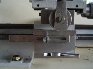
This is the new apron on the lathe. The lever at the bottom turns a disc with cams cut into it to push the half nut up and pull it down.
For those unfamiliar with the Perris (and its derivative, the modern Cowells) there is a dog clutch on the leadscrew, which can be operated manually, and can be also be used as an auto-stop, operated by the bar shown here. The slot is for adjustment of the stop position.
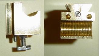
Here are two views of the half nut. A pushrod for the cam to act on runs vertically through the nut, and is threaded M3 for adjustment of the engagement of the nut with the leadscrew. The thread in the nut was left on the tight side at one end, so the pushrod won’t shift. A slot is provided at the top, and there is a corresponding hole in the top of the frame for screwdriver access. Initially, I though that only the pushrod would be needed, and that the nut would disengage itself easily with the assistance of two small springs in the holes in the top of the nut, but as mentioned below the nut needs a positive downward pull to begin disengagement. So, a “pullrod” had to be added, and one or other end of the bar on the pullrod engages with a cam on the underside of the cam disc. The pullrod is threaded M3, so the two ends of the bar combined with the 0.5mm pitch allow adjustment in increments of 0.25mm.
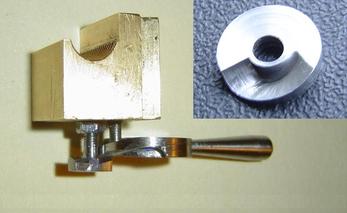
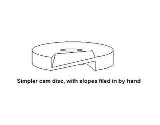
This shot is posed to show the relationship between the nut and the cam disc. The inset shows the top of the disc, before the operating lever was added. The helical cams were hard to make with my limited equipment, and the sketch below shows what might be a simpler method.
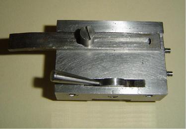
The apron off the lathe, with the leadscrew dog clutch actuator bar attached. The frame comprises a top 7mm thick, a front 12mm thick with a female dovetail on its inside, and a bottom 8mm thick to support the cam disc, which revolves around a 6mm pin. The front is not thick enough to lie beneath the existing holes in the saddle, so the top is needed to bridge the gap. The top, front and bottom are bolted together with M5 Allen screws, whose heads sit in counterbores. Space is tight, so the bolt heads had to be reduced in height so they would not sit proud of surfaces, and in diameter.
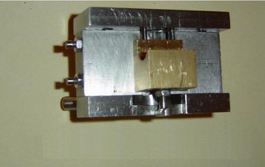
A back view of the completed apron. The springs (from 5 for £1 cigarette lighters at Pound World) are visible above the nut. Small depressions were drilled in the top plate of the apron to locate the springs, which have panel pins hung inside them to stop them buckling when compressed. There is a little gib in the dovetail, adjusted by the locknutted M3 screws visible at the side of the apron.
I worried that interaction between the 60° threads on the revolving leadscrew and the half nut might, under pressure, bend the leadscrew upwards. However, though the forces involved at the bottom of the U shaped half nut tend to do that, it transpired that stronger sideways forces towards the tops of the U exert enough friction to hold the nut and leadscrew together. As mentioned above, I had hoped that the cam would only have to push the nut up, and that the nut would self eject if assisted by light springs, but even a fairly strong spring from a clothes peg was insufficient to detach the nut when the leadscrew was turning. In the end, I had to form another cam on the underside of the disc and add the “pullrod” to give the nut an initial tug downwards as the lever is moved to the disengaged position.
A few odd points for anyone wanting to design something similar:
1. I found it easiest to make the half nut (using a home-made silver steel tap to create an M10 x 1 LH thread) and cam disc first, and make the frame to accommodate them. The gib and gib screws were then added, followed by the pushrod. The apron was then offered up to the saddle and the half nut engaged, so the positions of the tapped holes for bolts could be marked through the existing holes in the saddle (being the holes for the bolts which held the original solid nut). This ensured that the half nut was properly aligned with the leadscrew when the apron was installed. After installation, test runs revealed that the pullrod and another cam on the underside of the disc were needed as a fix for the disengagement problem.
2. The U-shaped half nut must move 2.5mm to separate the leadscrew from the threads at the tops of the U..
3. The bottom of the apron must be high enough not foul one of the bolts holding the lathe’s foot down; this is the brass nut in the first picture on this page.
4. My apron projects about 7mm further forward than the original nut, so the dog clutch actuator bar needs modification. The position of the bolts holding the apron frame together precluded milling a slot for the bar, so the top of the frame juts out a further 3mm to provide a ledge to locate the bar’s upper surface.
5. No new holes needed to be made in the lathe and the original solid nut can be reinstated if desired.
6. Materials: Frame and pullrod - mild steel. Nut – brass (though bronze would be more durable). Cam disc and pushrod – silver steel, hardened and tempered.
