Steve's WM180 Modifications.
Like me, Steve of Middlesborough owns a Warco WM180, which he uses to build his live steam Gauge 1 locos. But (unlike me!) Steve knows what he's doing, because he is a turner by trade. .
He reports that it is unwise to run the motor for more than 30 minutes per hour, particularly on large diameter jobs where low speed and high torque is involved. He burned out both motor and control board after four hours’ continuous running when reducing a 3” OD steel tube to 2.25”, and boring its ID out from 1” to 2”. To reduce the risk of this happening again, he fitted a new control board with overload protection (absent from the standard board) and arranged forced air cooling for the motor, because its internal fan doesn’t do much when the motor is running slowly. I have squeezed a computer fan in behind my motor, as shown here.
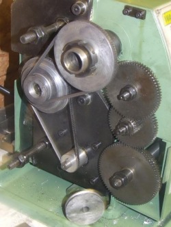
Steve made a 1” motor pulley, just over half the size of the standard one, for lower speeds with decent torque - useful on relatively large diameters, like the one which let the smoke out of his motor. This photo shows the new pulley in place, and the old one below for comparison. The smaller pulley leaves slack on the drivebelts, requiring a small mod to the belt tensioner. Like Steve, I fitted a smaller pulley, and had to add a couple of spacers, as shown by the yellow arrows on the photo at the bottom of this page.
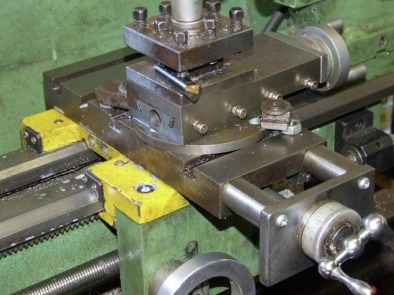
There's a lot in this picture! Note the cross-slide with a new feedscrew bracket attached to it rather than to the saddle, and the disc and clamp arrangement used when swivelling the topslide. The original cross-slide is too shallow to take the T-slots Steve wanted, so he obtained an old Myford one complete with feedscrew and nut, renovated it and fitted it using a wider than normal gib strip to fill the gap.
The feedscrew bracket is fixed to the cross-slide, with the feedscrew nut attached to the carriage. This reverses the standard WM180 arrangement, which requires the bracket to be long enough for the cross-slide to move out above it. Steve's bracket moves in and out with the cross-slide.
The feedscrew bracket is fixed to the cross-slide, with the feedscrew nut attached to the carriage. This reverses the standard WM180 arrangement, which requires the bracket to be long enough for the cross-slide to move out above it. Steve's bracket moves in and out with the cross-slide.
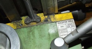
This shows the nut for the Myford feedscrew attached to the front of the saddle. It is much coarser pitch and better made than the original, though it is imperial and the rest of the lathe is metric, so Steve must be getting good at multiplying and dividing by 25.4!
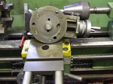
Here’s a shot of the underneath of Steve’s topslide. He cut away the underside of its base to leave a raised boss. A cast iron disc (recycled - hence the spare holes) fits round the boss and is bolted up to the base. A small spigot fits into the hole in the cross-slide. The disc enables the topslide base to be clamped down, using the clamps fitted wherever is convenient in the front two T-slots as shown earlier.
The additional height introduced by the deeper cross-slide meant that Steve had to remove metal from under his toolpost, to get 8mm tools back down to centre height The topslide sits higher, so it can now be swivelled 360° without its handle and dial fouling those of the cross-slide.
The additional height introduced by the deeper cross-slide meant that Steve had to remove metal from under his toolpost, to get 8mm tools back down to centre height The topslide sits higher, so it can now be swivelled 360° without its handle and dial fouling those of the cross-slide.
