A SEMI-AUTOMATIC SADDLE STOP.
When plain turning up to a shoulder using power feed, it can be hard to disengage the half nuts at just the right moment before the tool crashes into the shoulder. Even quicker reactions are needed when screwcutting, because the saddle moves much faster. The device described here addresses these problems. On repeated cuts, it stops the saddle in the same place, plus or minus 0.002”.
The concept is that once the half-nut lever (“the lever”) has been pushed down to start the saddle in motion, a latch locks it so it can’t be lifted until the saddle has reached an adjustable stop. If the lever is pulled up towards the end of a cut, it will not move until the stop unlocks the latch, but as soon as unlocking occurs, the lever is free to move so the upward pull on it unclasps the half nuts to bring the saddle to a halt.
Thus, the device needs to be in two parts: a latching mechanism mounted on the apron, and an adjustable stop fastened to the lathe bed or (more conveniently on the WM180) to the headstock. It would be nice to have the half-nuts disengaged by a spring, so the saddle halts at the desired point all by itself – that would be fully automatic. But the spring would have to be pretty powerful to disengage the half-nuts at the end of heavy cuts, when their reaction against the leadscrew thread might prevent easy disengagement. Accordingly, the device needs a hand pulling upward on the half-nut lever towards the end of a cutting pass; hence “semi-automatic”.
A further requirement was for the device to be easily disabled, without unbolting anything, to return the lathe to normal operation.
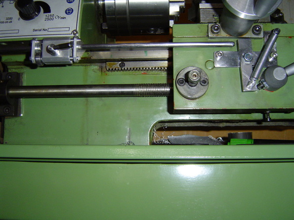
The following picture is a general view of the auto-stop. For clarity, the saddle handwheel has been temporarily removed. As can be seen, the cover under the headstock front has been dispensed with; it didn’t seem to guard me from any dangerous moving parts*. This allowed a bracket to be fixed under the front projection of the headstock. The bracket carries the stop, which is a long rod. The distance from the bracket to the end of the rod can be adjusted, to set the stop point at the required position. The latching mechanism can be seen on the front of the apron.
* On newer machines, the grey plate on the front of the headstock extends downwards over the leadscrew cover. It would need to be shortened if this modification is carried out.
The concept is that once the half-nut lever (“the lever”) has been pushed down to start the saddle in motion, a latch locks it so it can’t be lifted until the saddle has reached an adjustable stop. If the lever is pulled up towards the end of a cut, it will not move until the stop unlocks the latch, but as soon as unlocking occurs, the lever is free to move so the upward pull on it unclasps the half nuts to bring the saddle to a halt.
Thus, the device needs to be in two parts: a latching mechanism mounted on the apron, and an adjustable stop fastened to the lathe bed or (more conveniently on the WM180) to the headstock. It would be nice to have the half-nuts disengaged by a spring, so the saddle halts at the desired point all by itself – that would be fully automatic. But the spring would have to be pretty powerful to disengage the half-nuts at the end of heavy cuts, when their reaction against the leadscrew thread might prevent easy disengagement. Accordingly, the device needs a hand pulling upward on the half-nut lever towards the end of a cutting pass; hence “semi-automatic”.
A further requirement was for the device to be easily disabled, without unbolting anything, to return the lathe to normal operation.
The following picture is a general view of the auto-stop. For clarity, the saddle handwheel has been temporarily removed. As can be seen, the cover under the headstock front has been dispensed with; it didn’t seem to guard me from any dangerous moving parts*. This allowed a bracket to be fixed under the front projection of the headstock. The bracket carries the stop, which is a long rod. The distance from the bracket to the end of the rod can be adjusted, to set the stop point at the required position. The latching mechanism can be seen on the front of the apron.
* On newer machines, the grey plate on the front of the headstock extends downwards over the leadscrew cover. It would need to be shortened if this modification is carried out.
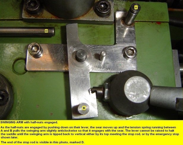
Rather than wordy descriptions, I trust the following story, told largely in pictures, will show the construction of the various parts and how they fit and work together. In summary, when the half-nuts are engaged with the leadscrew, the saddle moves left during the cut, eventually bringing a vertical swinging arm into contact with the end of the stop rod. The rod causes the arm to tip slightly, thereby disengaging a sear on the boss of the half-nut lever, unlocking it and allowing it to be lifted. An emergency stop is provided, allowing immediate manual disengagement if disaster looms.
Apologies for the machining marks; it may not be pretty, but it works!
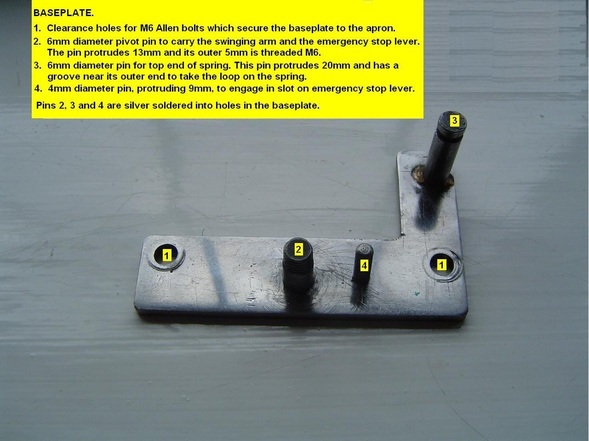
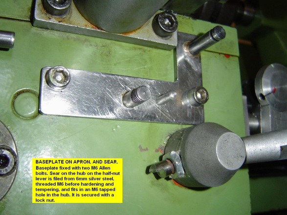
1. The baseplate and sear
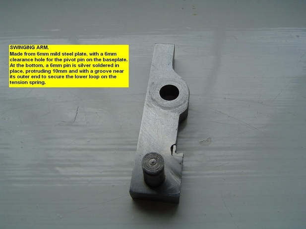
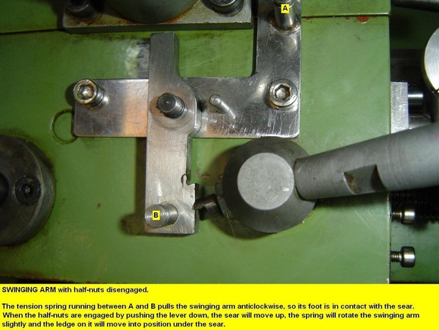
2. The Swinging Arm
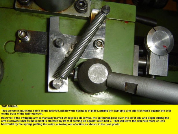
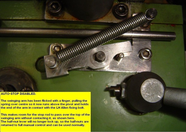
Some of the following pictures are posed without the tension spring fitted; it would obscure the detail beneath it. In the first picture, note the scrap of silver steel, silver soldered into the notch for wearing purposes. There was no point in hardening this, because the heat and cooling involved in soldering would anneal it. It would have been better to case harden the whole swinging arm.
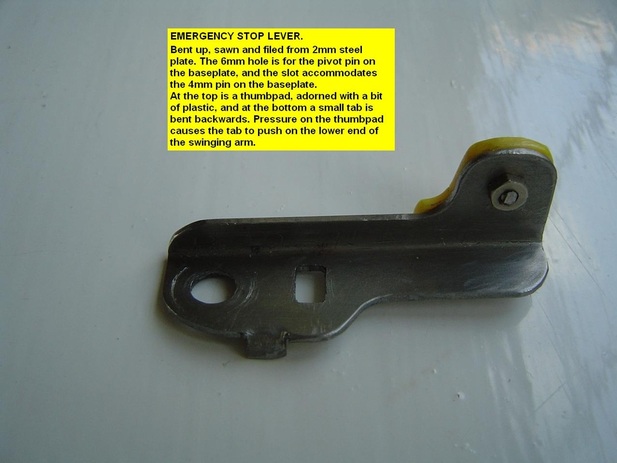
3. The Emergency Stop
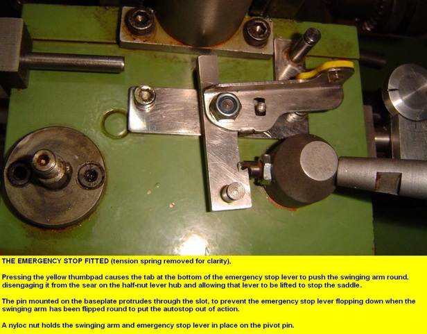
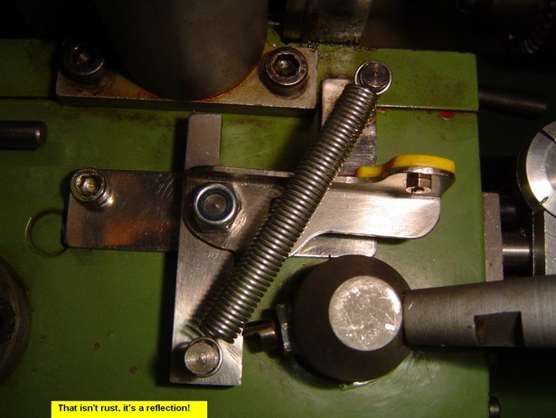
4. The complete latch assembly fitted to the apron.
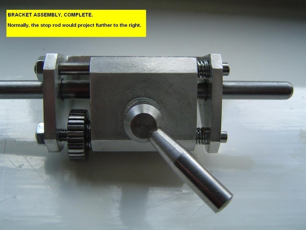
5. The Stop Rod Bracket and the Guide Block for the Stop Rod.
This needs a bit more explanation than will fit into short captions in pictures.
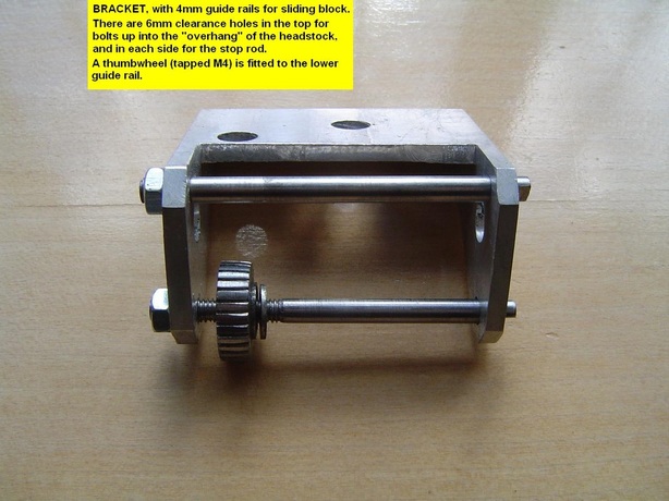
The first picture shows the complete assembly: a block which clamps the stop rod when the small handle is
tightened, the block itself sliding on guide bars within the bracket. Coarse adjustment of the stop rod is
achieved by moving it to suit the required stopping point and clamping it up. Fine adjustment is via the
thumbwheel, which pushes the block along the guide bars against spring pressure.
The second picture shows the assembly minus the clamp block. The bars are 4mm diameter, threaded M4 at
the LH end to screw into threaded holes in the LH side of the bracket, with locknuts on the outside. The other
end of each bar runs through a plain hole in the RH side of the bracket. The thread on the lower bar continues
inside the bracket to take the thumbwheel. Light springs keep the block pressed against the thumbwheel.
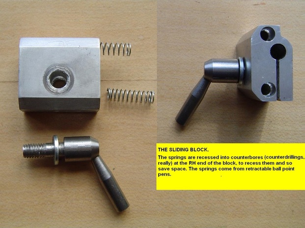
As shown in the third photo, the 4mm holes through the block for the guide bars are counterbored at the RH
end so most of each spring is hidden within the block.
I forget why the 6mm fixing holes in the top of the bracket are so oddly spaced, but it may be something to do
with where I could drill (5mm, then tap M6) through the underside of the headstock. Rather than turning the
lathe upside down, the drilling was done by unscrewing the curved front panel from the headstock and moving
it gently aside (unplug lathe first; the wiring to the speed control is at half mains voltage) and using an
old -fashioned hand drill of the grasp the handle, turn the crank on the side type, with a long 5mm bit. Drill
those holes first, then offer up the bracket and mark for the holes in it - doing it the other way round would
be difficult. Again, I forget how I did the tapping, but probably used a chuck type holder from below, with a
tommy bar I could shift from side to side as I turned it.
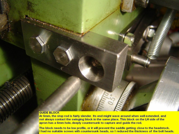
The fourth picture is of a simple device to guide the end of the stop rod.
A couple of notes on using the auto-stop.
When threading, it is not really necessary to cut a runout groove where the thread is to end. At the end of each pass, the half-nuts will disengage at the same point, halting the saddle with the spindle still rotating. The tool will thus cut a runout groove as threading progresses.
My emergency stop is on a hair trigger, so I don't rest my thumb on it during a pass in case I disengage the half-nuts prematurely,. Though that might not be a problem when plain turning, when screwcutting it would cause the tool to cut an annular groove and ruin the thread.
A useful addition.
I have been meaning to make a simple saddle stop for some time, for the saddle to come up against when feeding it manually with the handwheels on my apron or leadscrew. Usually, such a stop clamps to the front bedway, and often has a threaded rod through it for fine adjustment.
Looking at my auto-stop, it struck me that a simple collar which could be clamped to the stop rod would do the trick. The collar needed to be bigger than the countersunk hole in the guide block, so it would bump up against the side of the block rather than fit down the hole, but small enough not to foul the bolts which hold the guide block.
Coarse adjustment is by sliding the rod in and out of the bracket, or by clamping the collar in different positions along the rod with the clamp screw, which has a tiny brass slug beneath to protect the rod. Fine adjustment is by operating the thumbwheel in the stop rod bracket. Keen observers will note that the RH ends of the guide bars in the bracket have been cut back flush; their ends have been slotted for a screwdriver to assist in fitting them.
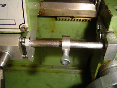
In use, it is as well to have some of the stop rod projecting beyond the collar, so that the guide block will capture the stop rod and stabilise it. To allow for this, the auto-stop latch can be disabled as described earlier.
This accessory doesn't have the sophistication of a turret which can be rotated to bring different stops into action, but it was certainly simple to make.
Back to Home and the Index
This accessory doesn't have the sophistication of a turret which can be rotated to bring different stops into action, but it was certainly simple to make.
Back to Home and the Index
