MOTOR COOLING
As the page about his improvements shows, WM180 owner Steve reported burning out his motor during prolonged turning of a large diameter item. In that situation the torque will be high and the motor rpm will be low, so the motor's internal fan will be doing very little when it is most needed. Incidentally, when the motor is running forward, the internal fan draws air in through the back and pushes it out of the front, the front being the pulley end.
It struck me that a computer fan, running continuously whether or not the lathe motor was turning, might do the job. Removing the chip guard revealed about 25mm space between the end of the motor and the bed casting.
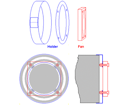
A 60mmx18mm thick 12V dc computer fan cost about £5. A housing for it, resembling the base of a large shoe polish tin with a 60mm hole cut in its bottom, was fabricated from thin steel sheet as shown in the sketch below.The annular side wall was formed by bending round a former (a paint can), and the ends joined with a patch soft soldered in place. The diameter (about 83mm) was arranged to be a firm push fit on the back end of the motor. A disc was snipped out from 0.5mm steel (an olive oil can), and the 60mm hole cut into it using compasses holding a sharp scriber (easier than it sounds). 3mm fixing holes for the fan were drilled. The disc was soft soldered to the annular portion, and the fan attached with M3 screws and nuts. As will be seen from the sketches, the 60mm fan is smaller than the outer ring of vents in the motor. The M3 screws were left long enough to stand the end of the fan housing about 5mm off the end of the motor so all the vents were exposed to the air flow.
The fan had three wires: red, black and blue. The blue is for a tachometer, I understand, so it was cut off short. The red has to go to +12V, and the black to 0V; the fan won't run in reverse. It was screwed to the housing with its label inwards, so the airflow would be into the motor. For protection, a bit of mains flex outer sheathing was slipped over the red and black wires, and an inline socket added to match the little plug on a 12V, 250mA wall transformer.
To turn my lathe off completely (speed indicator lights off), I use a switched wall socket. So the fan would run continuously whenever the lathe was turned on, I plugged both the lathe and the transformer into a two-way adapter in the wall socket.
When the lathe motor is run in reverse, its internal fan blows in the opposite direction to the new one, but the latter is more powerful and seems to win the fight. In any event, only rarely is the lathe under any appreciable load when its motor is reversed.

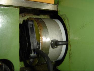
This was taken from the back of the lathe (chip guard removed) to show the fan in place.
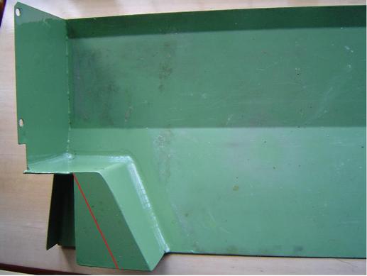
To accommodate the fan, the box in the chip guard had to be reworked so it was longer. The red line in the photo below shows where it used to end. A large hole was cut into the back of the chip guard behind the box, to admit air to the fan.
I added fillets of epoxy putty in the corners around the box, so chips would be easier to sweep away


